Bordcomputer (MID) im Astra G nachrüstenEs gibt grob gesagt 2 Möglichkeiten für die BC Nachrüstung
die Basic-Version dient hierbei der Arbeitserleichterung um schnell und einfach die wesentlichen BC-Funktionen zur VerfĂĽgung zu haben
Version 1 - Basic
Aktive Funktionen:- Reichweite
- Durchschnittsgeschwindigkeit
- Momentanverbrauch
- Durchschnittsverbrauch
- Stoppuhr
- PrĂĽfung der Bremslichtsicherung
Version 2 – Volles Paket (Wie ab Werk auch)
Aktive Funktionen:- Reichweite
- Durchschnittsgeschwindigkeit
- Momentanverbrauch
- Durchschnittsverbrauch
- Stoppuhr
- PrĂĽfung der Bremslichtsicherung
- Scheibenwasserkontrolle
- KĂĽhlwasserkontrolle
- Ăśberwachung des Bremsbelags vorn
- GlĂĽhlampenkontrolle (Abblend-, RĂĽck-, Bremslicht)
- Ă–lstandkontrolle
Nötig ist das Basic Paket damit der BC überhaupt funktioniert, das volle Paket sollten nur die nachrüsten, die mit der Elektrik des Fahrzeugs vertraut sind...
Es können aber logischerweise auch nur einzelne Sensoren nachgerüstet werden z.B. nur Scheibenwasserkontrolle
Anmerkung: Die zahlen in den Klammern sind die Katalognr. aus dem Lieferprogramm des Herstellers
Die Bezeichnungen der Steckverbindungen sind aus Schaltplänen des Fahrzeugs entnommen
Paket «Basic»benötigte Teile:
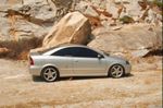
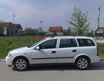
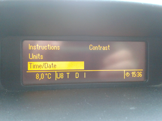
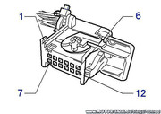
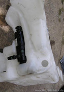
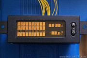
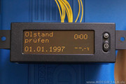
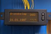
1. Multi Info Display MID (Foto 1, 2) Neupreis: 728,52 € nicht erschrecken gebraucht bekommt ihr das MID für ca. 150 €
es muss auch nicht genau dieses eine MID Display sein es gab mehrere verschiedene (siehe auch FAQ Ăśbersicht Display Arten)
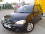
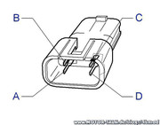
2. Lenkstockschalter mit Bedienknöpfen für BC (mit Heckwischer Funktion: 12 41 135 ohne Heckwischer Funktion: 12 41 134) (Foto 3) Neupreis: 79,90 € und 77,34 € gebraucht für ca. 15 € zu haben
3. ca. 5m Kabel 0,5 mm²
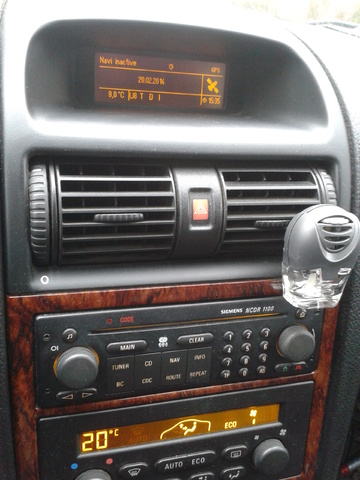
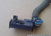
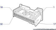
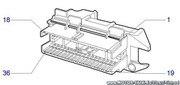
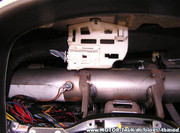
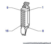
4. MID Stecker 32 Pin (Foto 4). Bild zeigt den Original Stecker wie er am Kabelbaum ab Werk (mit Bordcomputer) zu finden ist. Stecker und Pins gibt es bei Opel grundsätzlich nicht einzeln...(wenn doch dann nur als extrem überteuerte Reparatursätze)
fehlende Stecker sowie passende Pins gibt es aber gĂĽnstig als Neuware ĂĽber mich zu beziehen
Multi Info Display (MID):
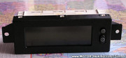
Multi Info Display (MID):
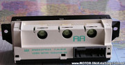
Lenkstockhebel mit BC Knöpfen:
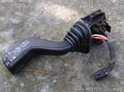
32-poliger MID Stecker:
 Anmerkung:
Es existieren viele Varianten des MID z.B. mit Zuheizer oder mit TelefonunterstĂĽtzung (Carphone MID)
Diese Anleitung handelt von einem "normalen" MID ohne jegliche Zusätze, denn dies
funktioniert immer und ĂĽberall...
aber auch die anderen MID Display's sollten sich ohne Probleme nachrĂĽsten lassen. (Bitte Programmierung beachten!)
Kommen wir nun zum Einbau: Das TID (Tripple Info Display) könnt ihr getrost rausschmeißen, denn es kann absolut gar nichts außer
die 3 Sachen anzeigen, was es ja auch macht. Aber der Stecker davon besitzt 12 Kabel die unbedingt nötig sind bei der Nachrüstung des MID.
12-poliger TID Stecker:
32-poliger MID Stecker:
Diese 12 Kabel sind aus dem Stecker des TID zu entnehmen und in den 32 pol Stecker einzusetzen,
dies ist möglich da die Pins absolut identisch sind.
Man nehme beide Stecker auseinander indem man:
1. den Kabelbinder durchschneide
2. den Schwarzen inneren Einsatz mit den Pins aus dem Gehäuse entferne indem man die Widerhacken
mit einem kleinen Schraubendreher wegdrĂĽcke und dabei am Kabelstrang ziehen muss.
Jetzt die Pins entnehmen.
Am einfachsten geht es mit einer Nadel, man drĂĽcke die Widerhacken und ziehe an jedem einzelnen Kabel.
Die Pins werden nach folgendem Schema wieder eingefĂĽgt:
Die Rot markierten Kabel sind vom TID vorhanden und mĂĽssen nur von einem Stecker in den anderen ĂĽbertragen werden.
Das blaue Feld erklären das Verbrauchssignal in einer extra Tabelle weiter unten.
Pin am MID -Stecker # Kabelfarbe # Funktion # Pin am TID -Stecker # Anschluss an # Einbauort falls vorhanden
1 # Braun # Masse # 6 # Vorhanden # Stecker TID
2 # BlauweiĂź # AuĂźentemperatur # 5 # Vorhanden # Stecker TID
3 # Blau # AuĂźentemperatur # 7 # Vorhanden # Stecker TID
4 # Schwarz # Sicherung 1.13 ab MJ2002 3.13 # 1# Vorhanden # Stecker TID
5 # Rot # Sicherung 3.34 ab MJ 2002 1.34 # 3 #Vorhanden # Stecker TID
6 # GrĂĽn # Drehzahlmesser # Instrumentenstecker (Tacho) Pin 20
7 # Graugelb # Multitimer/MUT # 4 # Vorhanden # Stecker TID
8 # RotweiĂź # Radio/EMP (Radio Infos,Datum etc..) # 2 # Vorhanden # Stecker TID
9 # Braunrot # Radio/EMP # 10 # Vorhanden # Stecker TID
10 # Braungrau/grĂĽn # CD -Wechsler/Autotelefon # 12 # Vorhanden # Stecker TID
11 # Braunschwarz/weiĂź # CD - Wechsler/Autotelefon # 11 # Vorhanden # Stecker TID
12 # Blaurot # Wegstreckengeber/WEG # 9 # Vorhanden # Stecker TID
13 # BraungrĂĽn # Sensor Ă–lstand # Kontrollschalter Ă–lstand oder Masse # Neu legen!
14 # BraunweiĂź # Diagnosestecker # 8 # Vorhanden # Stecker TID
15 # Schwarzgelb # Bremslichtschalter # Bremslichtschalter direkt Pin 2 bei zweipoligem oder Pin 3 bei 4poligem Schalter
16 # Schwarz # Sicherung 1.38/Bremslicht ab MJ 2002 3.38 # Sicherung 38 oder Bremslichtschalter direkt Pin 1 bei zweipoligem Schalter oder Pin 4 bei 4 poligem Schalter # Sicherungskasten
17 # WeiĂźgrĂĽn # GlĂĽhlampenkontrolle # GlĂĽhlampenkontrolle Pin 1 oder Masse # Neu legen!
18 # Schwarzgelb # GlĂĽhlampenkontrolle # GlĂĽhlampenkontrolle Pin 2 oder offen! # Neu legen!
19 # Gelbrot # Sensor Bremsbelag # Kontrollschalter Bremsbelag oder Masse # Neu legen!
20 # Braunblau # Sensor KĂĽhlflĂĽssigkeit # Kontrollschalter KĂĽhlmittel oder Masse # Neu legen!
21 # Unwichtig war mal fĂĽr Automatikgetriebe vorgesehen bis MJ 2000
22 # Braungelb # Sensor WaschflĂĽssigkeit # Kontrollschalter WaschflĂĽssigkeit oder Masse # Neu legen!
23 # BraunweiĂź # Lenkstockchalter MID / A # Zum Lenkstockschalter weiĂź # Neu legen!
24 # Braunrot # Lenkstockschalter MID / D # Zum Lenkstockschalter rot # Neu legen!
25 # Nicht belegt
26 # Blauschwarz # Tankgeber # Instrumentenstecker# Pin 25 # Instrument
27 # Schwarzbraun # Verbrauchsignal(Steuergerät) # Motorabhängig # Alle Motoren
28 # Braun/Grau nur bei MJ 2001-2002# Bremslichtschalter# Pin 2# bei allen Motoren ausser Y20DTL/Y20DTH/X16XEL und Z20LET
29# Grau/GrĂĽn # Nur bei Zuheizer # X6 Pin 8
30# Schwarz/Grau # Nur bei Zuheizer # X6 Pin 9
31 # Blau # KĂĽhlwassertemperatur / INS # Instrumentenstecker (Tacho) Pin 28
32 # Nur bei Zuheizer # X2 Pin 14
Verbrauchsignale am Motorsteuergerät: Z12XE # Stecker X 79 # Pin 52
X12XE # Stecker X56 # Pin 16
Z14XE / Z16XE + XEP / Z16SE # Stecker X 71 # Pin 47
Z14XEP # Stecker X52 # Pin 59
Z16YNG # Stecker X141 # Pin 47
X16SZR # Stecker X 55 # Pin 9
X14XE / X16XEL # Stecker X 53 # Pin 21
Z18XE und XEL # Stecker X 57 # Pin 20
X18XE1 und X20XEV # Stecker X 57 # Pin 5
Z20LET # Stecker X 125 # Pin 52
Z22SE # Stecker X 77 # Pin 8
Y17DT/DIT # Stecker X 73 # Pin 47
Y20DTL + DTH / X20DTL / X17DTL # Stecker X 59 # Pin 29
Y20DTH/Y22DTR mit PSG 16 # Stecker X 93 # Pin 26
Z17DT # Stecker X129 # Pin 12
auch hierfür ist meistens ein Pin für den Stecker am Motorsteuergerät notwendig
diesen bekommt ihr unter anderem auch bei mir (sofern vorhanden) je nach Motor unterschiedlich
Anmerkung zum Bremslichtschalter
X-Motoren immer 2 polig verbaut bei Tempomat auch der 4 polige
bei Z-Motoren immer grundsätzlich der 4 polige
zum 4 poligen:
bei den ersten Baujahren Betreff Modelljahre bis 98.5
waren Pin 3 und 4 andersherum belegt !
die Beschreibung oben bezieht sich auf alle ab MJ99
Stecker Instrument (Tacho):
Stecker Instrument (Tacho):
Gegenstecker vom Lenkstockhebel:
Anmerkung:
Wenn der Gegenstecker nicht aufzutreiben war, dann muss man den Lenkstockschalter direkt ohne Stecker anlöten.
Das dritte Anschlusskabel (braun) des Lenkstockhebels geht auf Masse
Paket «Voll» benötigte Teile:
1. Paket «Basic»
2. Glühlampenkontrolle (62 38 078) Neupreis: 80,47 € gebraucht für ca. 20 € zu haben idealerweise gleich mit Gegenstecker
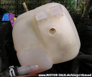
3. Kühlwasserbehälter mit Loch für Kühlwassersensor (13 04 223) (Foto 17) Neupreis: 31,48 €
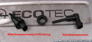
4. Kühlwassersensor (13 04 729) (Foto 16) Neupreis: 23,64 €
5. Bremsbelagsensor (2 St.) (12 38 442 oder 62 35 674) Neupreis ein Satz (2 Stück): 20,94 €
6. Ölstandsensor (Kat. Nr. Motorabhängig) mit Dichtung (Kat. Nr. Sensorabhängig) Neupreis schwankt zwischen 84 € und 110 €
7. Wischwassersensor (12 38 401) mit Dichtung (12 38 821) (Foto 16) Neupreis Sensor: 23,22 € Dichtung: 1,85 €
8. Ölwanne mit Loch für Ölstandsensor (Kat. Nr. Motorabhängig) Neupreis schwankt zwischen ca. 180 € und 230 €
9. Bohrmaschine und Bohrer mit 19mm Durchmesser
10. 8m Kabel 1,5 mm²
11. 10m Kabel 0,75 mm²
12. Multimeter
Wischwasser- und KĂĽhlwassersensor:
Kühlwasserbehälter mit Loch für Sensor:
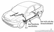
Der Anschluss der ganzen Sensoren ist simpel, jeder Sensor hat 2 Kabel wobei einer auf Masse gelegt wird und der andere zum 32 Poligen Stecker vom MID gezogen wird...dabei gibt es eine Besonderheit bei den Bremsbelagsensoren, diese weiden nämlich in Reihe geschaltet, d.h. Pin 1 vom linken Sensor wird am MID angeschlossen Pin 2 geht rüber zu Pin 1 am rechten und Pin2 vom rechten geht an Masse.
Dabei benötigt man noch die ganzen Gegenstecker für die Sensoren die jedoch auf Schrottplätzen etc. zu finden sind, da es ganz einfache Stecker sind die auch wo anders verbaut wurden.
Wischwassersensor:
Wischwasserbehälter mit Loch für Sensor gibt es nicht. Alle werden verschlossen ausgeliefert. Aber jeder Behälter hat unten rechts eine kleine Vertiefung, die für den Sensor gedacht ist. Hier kommt der Bohrer ins Spiel. Man muss ein 19mm loch an dieser Stelle in den Behälter bohren.
ACHTUNG: Das loch muĂź exakt 19mm im Durchmesser haben. ansonsten ist es entweder undicht oder ihr bekommt den Sensor nicht hinein.
Wischwasserbehälter:
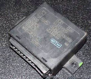
GlĂĽhlampenkontrolle:
Diese ist dafür gedacht, einen Fehler zu melden, falls eine der überwachten Lampen defekt ist. Es werden die Abblend-, Rück- und Bremslichtlampen überwacht, indem das Steuergerät in die Zuleitung zwischen der Sicherung und der einzelnen Lampen geschaltet ist. Das Signal wird dann ans MID weitergeleitet und dort angezeigt. Es sollte ein zentraler Ort gesucht werden, von dem man alle Leitungen gut erreichen kann (z.B. Da wo das normalerweise sitzt, hinter dem Beifahrerairbag) Falls auch dieses Steuergerät nicht vorhanden ist, müssen am Stecker der Pins 17 auf Masse gelegt werden, der Pin 18 bleibt offen! (wichtig)
Steuergerät für Glühlampencontrolle (CC):
Stecker GlĂĽhlampenkontrolle:
Hier die Belegung fĂĽr die GlĂĽhlampenkontrolle:
Pin # Funktion # Farbe
1 # an Pin 17 MID # WeiĂź-grĂĽn
2 # an Pin 18 MID # Schwarz-gelb
3 # ----- # -----
4 # ----- # -----
5 # Masse # Braun
6 # Hinter Sicherung Abblendlicht links # Gelb
7 # Hinter Sicherung Abblendlicht rechts # Gelb
8 # an Lampe Bremslicht links # Schwarz-gelb
9 # an Lampe RĂĽcklicht links # Grau-schwarz
10 # an Lampe RĂĽcklicht rechts # Grau-rot
11 # Hinter Sicherung RĂĽcklicht links # Grau-schwarz
12 # Hinter Bremslichtschalter # Schwarzgelb
13 # Hinter Sicherung RĂĽcklicht rechts # Grau-rot
14 # an Lampe Abblendlicht links # Gelb
15 # an Lampe Abblendlicht rechts # Gelb
16 # an Lampe Bremslicht rechts # Schwarz-gelb
Stromlaufplan GlĂĽhlampenkontrolle:
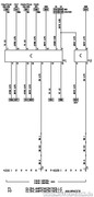
KabelfĂĽhrung im Astra G:
Vorher/Nachher GlĂĽhlampenkontrolle:

Danach alles anstecken Strom einschalten und ausprobieren.
Wenn ihr alles richtig gemacht habt sollte das MID jetzt funktionieren.
Startet mal den Motor und achtet auf den Verbrauch, die Durchschnittgeschwindigkeit und so weiter.. zeigt im Normalfall absolut merkwĂĽrdige Werte an, oder nur "Programm" wenn es Neu ist.
Da das MID (meistens jedenfalls) vorher in einem Astra gesessen hat, der nicht unbedingt denselben Motor und Steuergerät hatte, ist das MID auch genau auf diese Kombination programmiert. Damit ihr genau wisst, welchen Code ihr im Moment habt, drückt die Set und die Reset Taste zusammen gleichzeitig für ca. 3 sec, dann seht ihr die Codenummer, Softwareversion und die Impulse pro km.
Also, auf zum freundlichen Opelhändler und diesen bitten, das MID mit dem richtigen Programmcode zu versehen.
Viel SpaĂź mit dem Bordcomputer
Pixeltest:
Ă–lstand PrĂĽfen:
Waschwasser Stand:

Bremsbelag:
Fahrlicht RĂĽcklicht:

Bremslicht Sicherung:

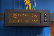
KĂĽhlmittel Stand:
EDIT:
bobale vec ostavio link, moze brisanje mog posta